Many thanks Shaun: I spent 7 happy years in Yorkshire, (I am a southerner by birth, and live there now), but fully subscribe to a Yorkshireman's values. I agree that many modern modelling gadgets are more ornament than use and therefore choose to save my limited funds. I am also trying to demonstrate to others that simple methods are often the best and well within the capabilities of most simple folk. And they don't come simpler than me!!
Lone Modeller's Tray
-
Lone Modeller
- Modelling Gent and Scholar
- Posts: 5345
- Joined: April 1st, 2013, 6:45 pm
Re: Lone Modeller's Tray
Many thanks Shaun: I spent 7 happy years in Yorkshire, (I am a southerner by birth, and live there now), but fully subscribe to a Yorkshireman's values. I agree that many modern modelling gadgets are more ornament than use and therefore choose to save my limited funds. I am also trying to demonstrate to others that simple methods are often the best and well within the capabilities of most simple folk. And they don't come simpler than me!!
-
MoMil

- Active Participant
- Posts: 673
- Joined: May 1st, 2011, 5:28 pm
- Location: Wigston, Leicestershire, UK
- Contact:
Re: Lone Modeller's Tray
Yet more amazing work LM, superb craftsmanship.
Cheers, Neale.
Close enough for government work
Close enough for government work
-
Impisi

- Modelling Gent and Scholar
- Posts: 2024
- Joined: November 6th, 2020, 10:28 pm
- Location: Germany
Re: Lone Modeller's Tray
cool, what a nice SBS build report - it looks amazing
-
Lone Modeller
- Modelling Gent and Scholar
- Posts: 5345
- Joined: April 1st, 2013, 6:45 pm
Re: Lone Modeller's Tray
Evening All,
Thank you Neale and Impsi for your kind comments - they are much appreciated.
I have made some progress with this project, but did have a case of two steps forward and one back, which meant that I had to dissemble and re-assemble some parts. I completed the addition of the interplane and boom struts after the initial assembly had dried out: this was a straightforward task as it involved gently placing the ends of the struts into the pre-drilled holes in the wings after I had place a small drop of glue into the relevant holes. The boom struts were cut to exact length and fixed in place with CA:
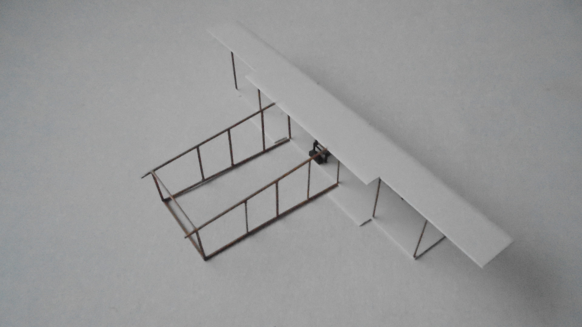

When I added the supporting struts for the upper wing overhang I did not cut them to the correct length and as a consequence I distorted the wing and boom structures. It took me a whole evening of fiddling and thinking before I realised the cause of the problem, by which time I had partially dissembled the top wing. Fortunately as soon as I removed the outermost interplane struts the problem was resolved: the wing was re-assembled and new outer struts cut and glued into place and all was square again.
I made the front booms from brass bar as the originals were square section. I measured the gap between the wings using a pair of dividers and marked the where the ends of the booms needed to be with a pencil on a piece of paper. I could then lay the brass bar on the paper to form two V's which I was able to solder:
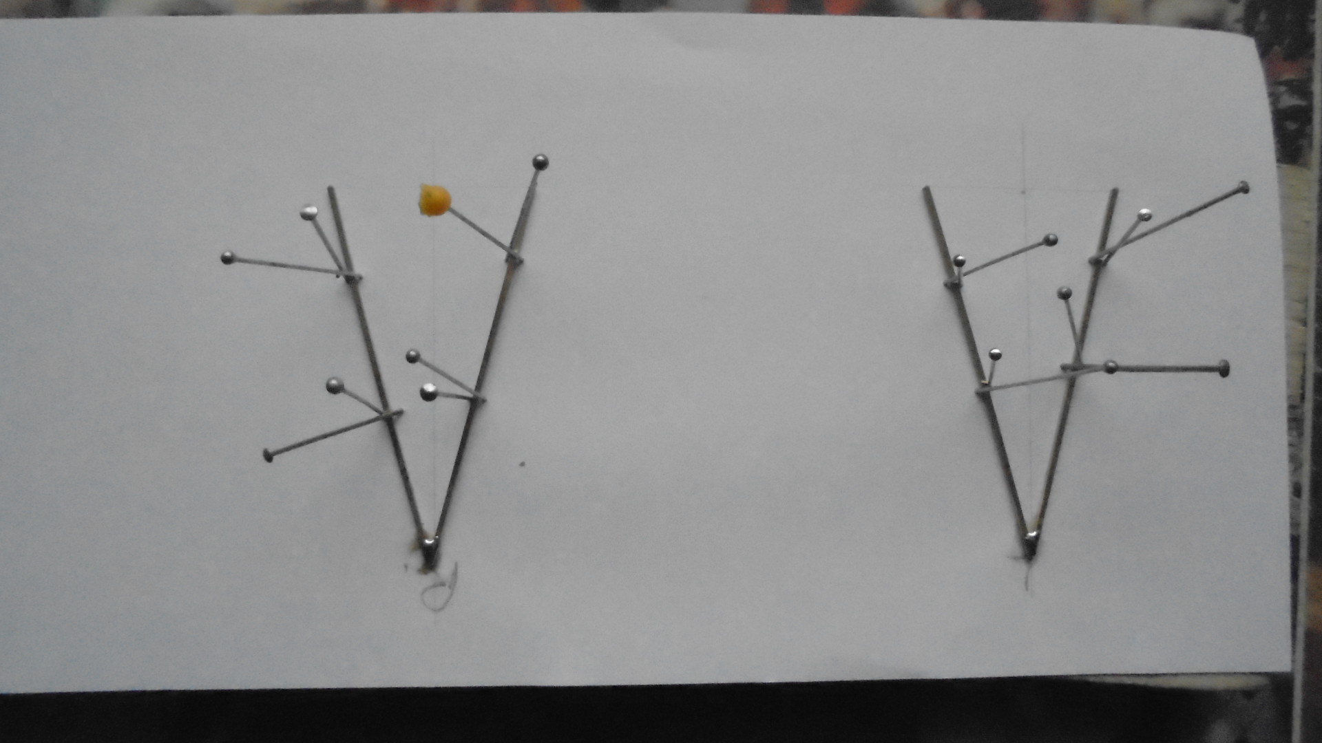
After the joints had been cleaned with a file I was able to CA the repective booms to each side of the front of the model. I started rigging the model at this stage because some areas will be difficult to reach later. The wings and boom bracing was rigged using rolled copper wire held with CA:

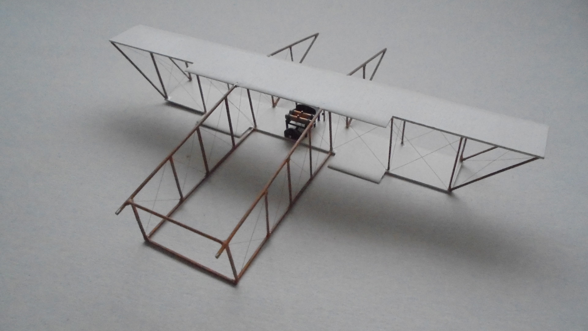
I have now reached a snag: the undercarriage was a simple structure consisting of two struts on each side supporting two skids. The axle ran across the skids. This will be an inherently weak part of the model which will require careful handling, especially when rigging. In addition if I finish the aircraft before I make the turret and foredeck on which I intend to mount it, I will have to be very careful in storing the aircraft model to stop it being accidentally damaged, so I have put it to one side for the moment while I concentrate on the base.
I have made a small start on the base but am still in the process of studying photos of the deck and turret to work out some of the smaller details. I am not a ship modeller so I am on a very steep (vertical?) learning curve at the moment, but in the last couple of days I have had access to some very helpful information with the help of a fellow modeller and I hope to be able to present the results of my research in model form before too long.
Thanks for looking.
Thank you Neale and Impsi for your kind comments - they are much appreciated.
I have made some progress with this project, but did have a case of two steps forward and one back, which meant that I had to dissemble and re-assemble some parts. I completed the addition of the interplane and boom struts after the initial assembly had dried out: this was a straightforward task as it involved gently placing the ends of the struts into the pre-drilled holes in the wings after I had place a small drop of glue into the relevant holes. The boom struts were cut to exact length and fixed in place with CA:
When I added the supporting struts for the upper wing overhang I did not cut them to the correct length and as a consequence I distorted the wing and boom structures. It took me a whole evening of fiddling and thinking before I realised the cause of the problem, by which time I had partially dissembled the top wing. Fortunately as soon as I removed the outermost interplane struts the problem was resolved: the wing was re-assembled and new outer struts cut and glued into place and all was square again.
I made the front booms from brass bar as the originals were square section. I measured the gap between the wings using a pair of dividers and marked the where the ends of the booms needed to be with a pencil on a piece of paper. I could then lay the brass bar on the paper to form two V's which I was able to solder:
After the joints had been cleaned with a file I was able to CA the repective booms to each side of the front of the model. I started rigging the model at this stage because some areas will be difficult to reach later. The wings and boom bracing was rigged using rolled copper wire held with CA:
I have now reached a snag: the undercarriage was a simple structure consisting of two struts on each side supporting two skids. The axle ran across the skids. This will be an inherently weak part of the model which will require careful handling, especially when rigging. In addition if I finish the aircraft before I make the turret and foredeck on which I intend to mount it, I will have to be very careful in storing the aircraft model to stop it being accidentally damaged, so I have put it to one side for the moment while I concentrate on the base.
I have made a small start on the base but am still in the process of studying photos of the deck and turret to work out some of the smaller details. I am not a ship modeller so I am on a very steep (vertical?) learning curve at the moment, but in the last couple of days I have had access to some very helpful information with the help of a fellow modeller and I hope to be able to present the results of my research in model form before too long.
Thanks for looking.
-
Stuart

- Raider of the Lost Ark Royal
- Posts: 19451
- Joined: February 25th, 2013, 4:55 pm
- Location: North Wales
- Contact:
Re: Lone Modeller's Tray
That is an insane bit of work LM - very nicely done! It's hard to believe they flew that off a ship!
Stuart Templeton I may not be good but I'm slow...
My Blog: https://stuartsscalemodels.blogspot.com/
My Blog: https://stuartsscalemodels.blogspot.com/
-
Softscience

- Staring out the window
- Posts: 7491
- Joined: April 5th, 2011, 4:34 pm
- Location: Maryland, near Washington DC
Re: Lone Modeller's Tray
can the landing gear be made from metal rod and soldered together for additional strength?
-
B4en

- Modelling Gent and Scholar
- Posts: 1145
- Joined: February 8th, 2014, 9:58 am
- Location: South Yorkshire
Re: Lone Modeller's Tray
Oh my, that is superb scratchbuilding LM!
The past, present, and future walked into a bar. It was tense.
-
iggie

- Modelling Gent and Scholar
- Posts: 23438
- Joined: July 31st, 2013, 11:04 am
- Location: North Somercotes, Lincolnshire
- Contact:
Re: Lone Modeller's Tray
If I soldered something that shape even at 1:1 scale it would look like a dog's dinner. To do it so nearly at 1/72 is impressive to say the least!
Best wishes
Jim
If you can walk away from a landing, it's a good landing. If you use the airplane the next day, it's an outstanding landing
"Never put off till tomorrow, what you can do the day after tomorrow"
Jim
If you can walk away from a landing, it's a good landing. If you use the airplane the next day, it's an outstanding landing
"Never put off till tomorrow, what you can do the day after tomorrow"
-
ShaunW
- NOT the sheep
- Posts: 26188
- Joined: November 26th, 2011, 6:11 pm
- Location: Pontefract West Yorkshire
Re: Lone Modeller's Tray
That looks superb, LM, although not achieved without difficulty which you overcame admirably.
Doing - Tamiya 1/35th Universal Carrier.
Work is the curse of the modelling classes!
IPMS#12300
Work is the curse of the modelling classes!
IPMS#12300
-
Lone Modeller
- Modelling Gent and Scholar
- Posts: 5345
- Joined: April 1st, 2013, 6:45 pm
Re: Lone Modeller's Tray
Evening All,
Many thanks for your (too) kind comments - they are greatly appreciated. I have given a lot of thought to the undercarriage problem but cannot drill holes under the wing because in the front there is a strut in the way, and at the rear the boom is where the undercarriage leg is to be attached. I will probably have to use butt joints which are not the strongest attachment, but I am hoping that if the model is secured to the launch platform it will have sufficient strength to hold properly.
I have become a ship modeller recently: usually I make aeroplanes so I am learning fast. When I dropped into my LMS and asked for a kit of the front turret and foredeck of an Edwaed VII class battleship of 1912 in 1/72 scale I just received a blank stare! I started by downloading a plan and side elevation of the foredeck of HMS Africa/Hibernia and enlarged it until 1mm represents 1 foot. I could then draw a plan at 1/72 scale where 1 inch represents 6 feet.
I have made a base which is 12 inches (30 cm) x 11 inches (28cm) from hardboard and painted the edges which will not be covered by the deck white. I used white rather than sea blue because this will not be a waterline model: only the top of the ship sides above the portholes of the crew accommodation will be represented. Three supports from 1 inch x 1 inch (2.5cm x 2.5 cm) wood were glued to the top of the hardboard - these will hold the deck. I shaped 2 pieces of 1 inch square wood to represent the sides of the ship immediately below the deck line and covered the outer faces with 10 thou plastic sheet. These will be painted battleship grey later. The small fillets at the rear of the sides represent the curve of the ship sides above a 9.2 inch gun mounted low down in the hull:
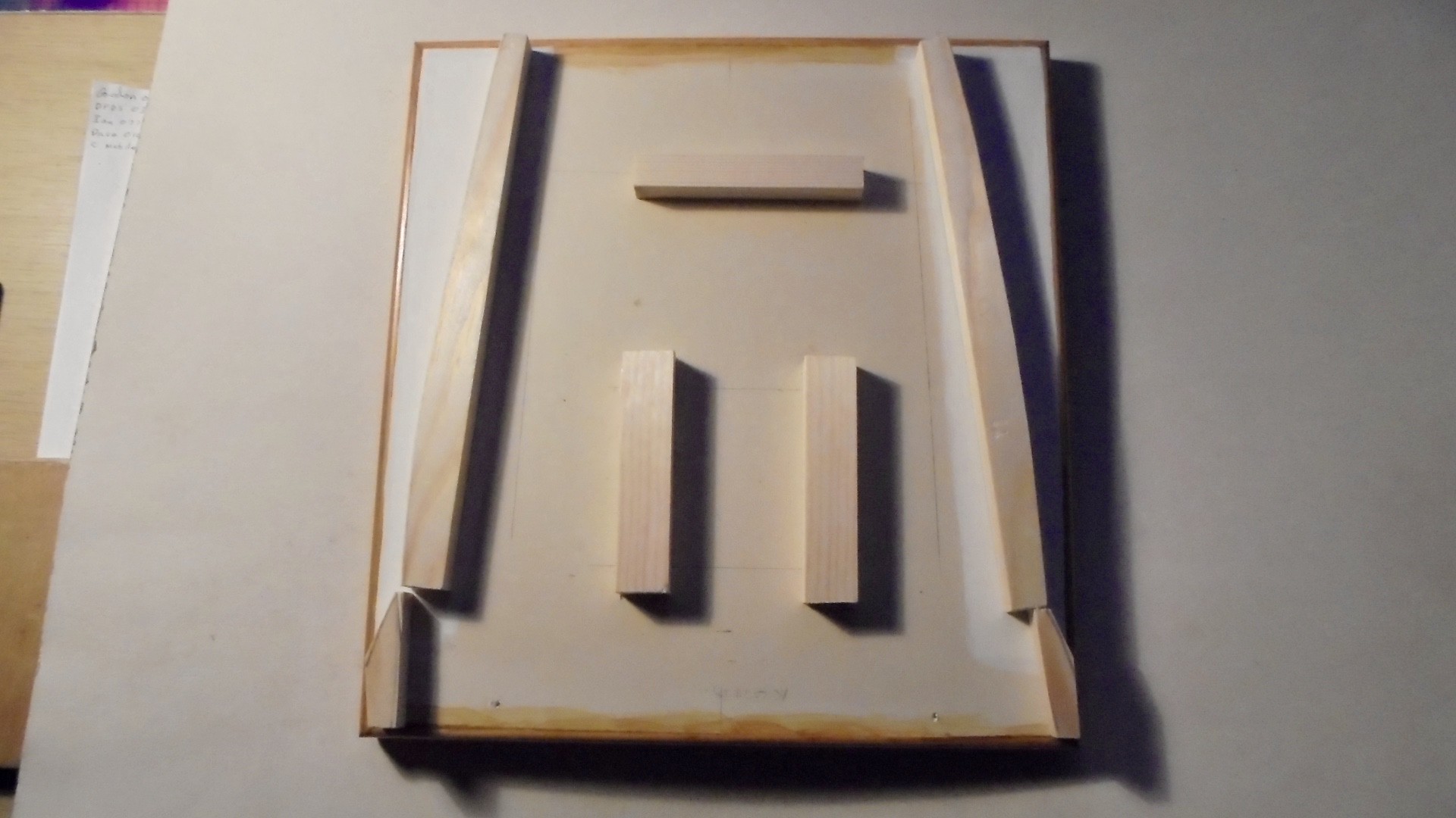
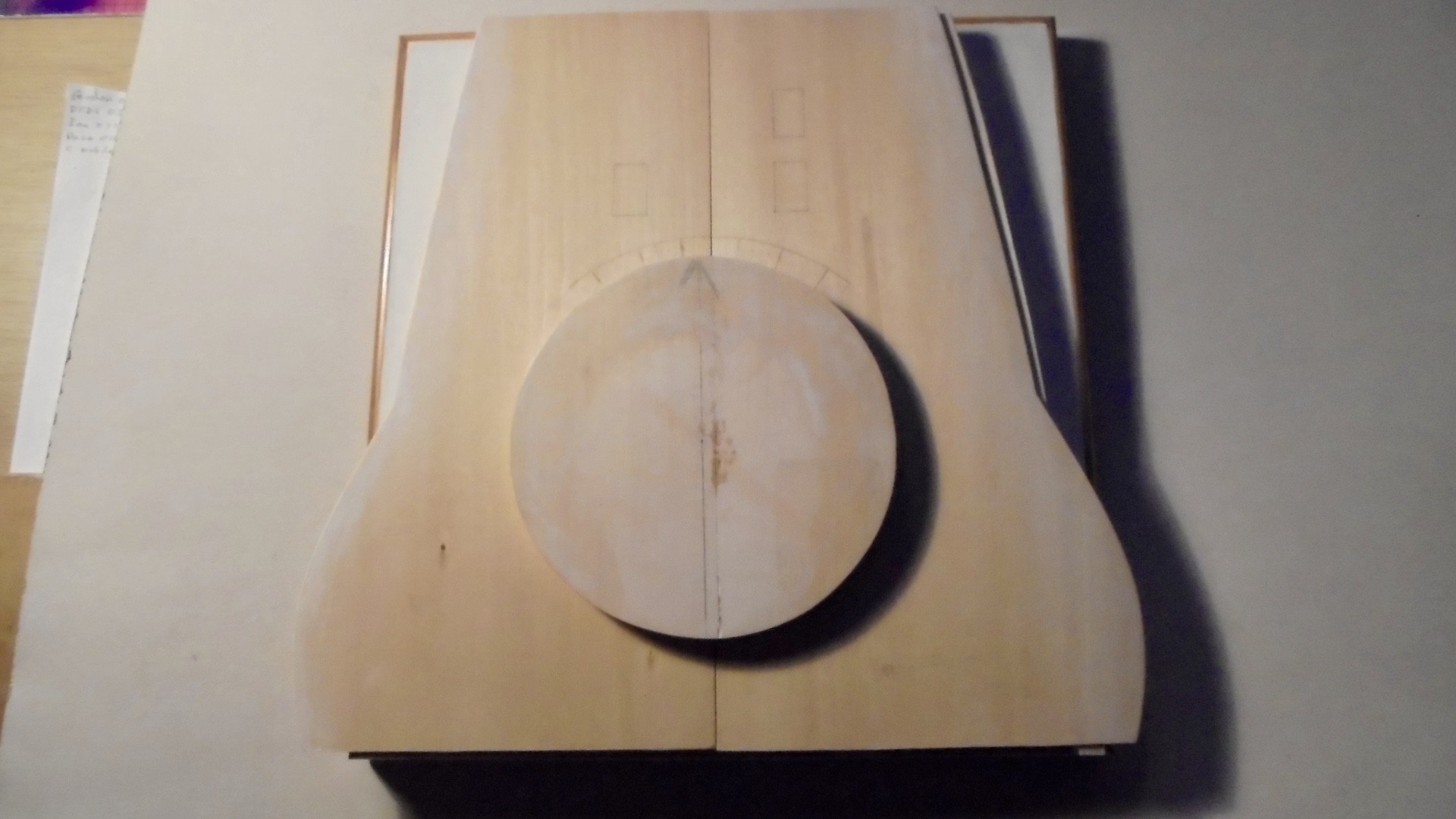
The gaps at the front and rear of the model between deck and base will be covered with plastic card later. The deck was cut form 1/8th inch (2mm) basswood (lime) sheet: 2 pieces were cut and shaped to represent the deck forward of the bridge to a point approximately 30 feet (8.2m) forward of the forward barbette breakwater. The edges were rounded with glass paper and sealed with a mixture of talcum powder and dope:

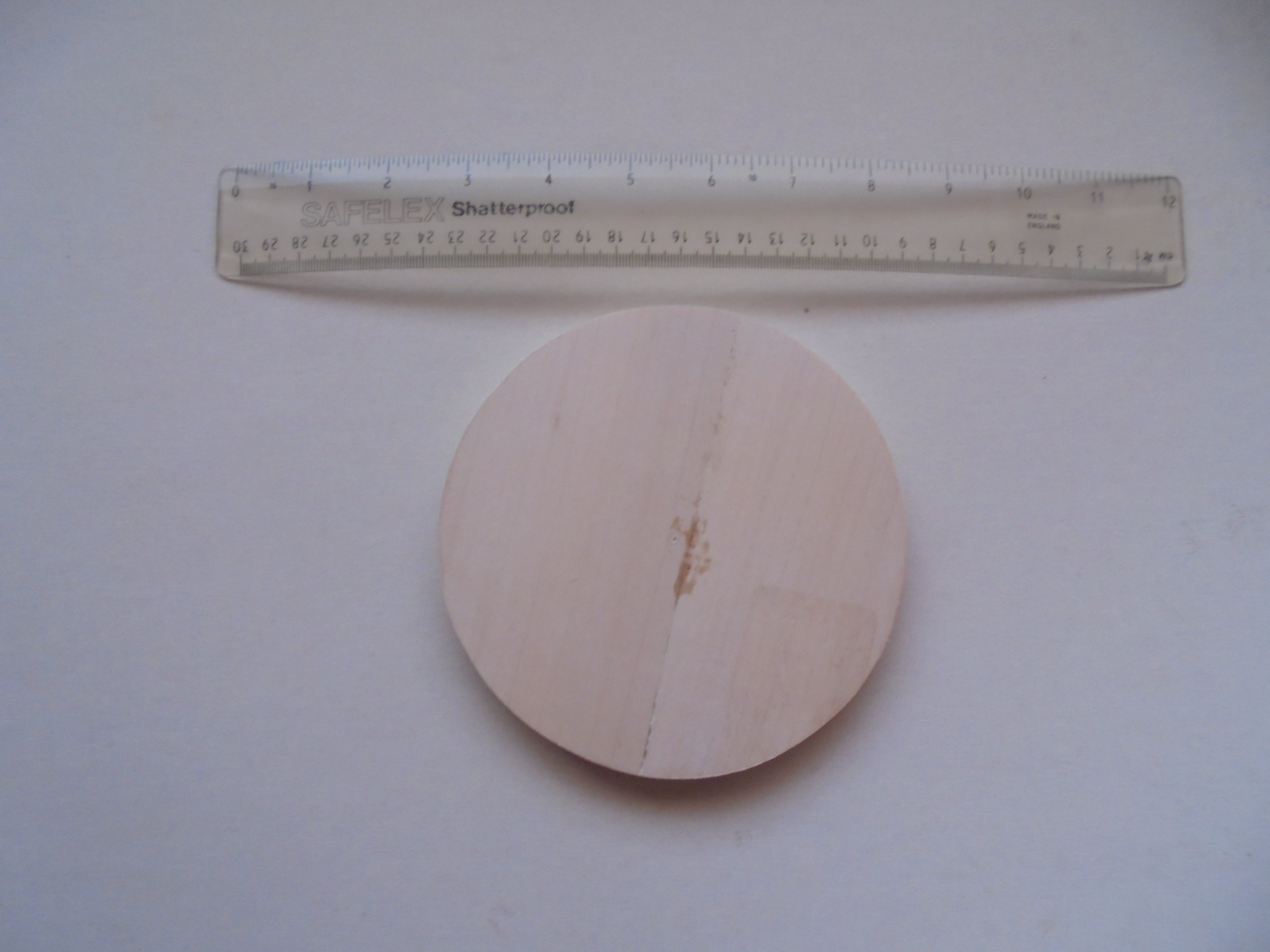
The circle and arc represent where the barbette and breakwater will be positioned later. The curved rear covered the 9.2 inch guns in the hull and will have 60th plastic sheet CA'd underneath to represent the armoured deck.The top of the deck will be covered with 1/8 inch (2mm) square pine strip to represent the wood planking on the real ships. The barbette was cut form 4 pieces of 1/4 inch (0.5mm) basswood sheet: 2 pieces were joined to form a square sheet and the two sheets glued so that the joints were at 90 degrees. When the glue had set I cut off the waste wood around the circle that I had drawn on one surface, and the final rounding was achieved with a wood file:

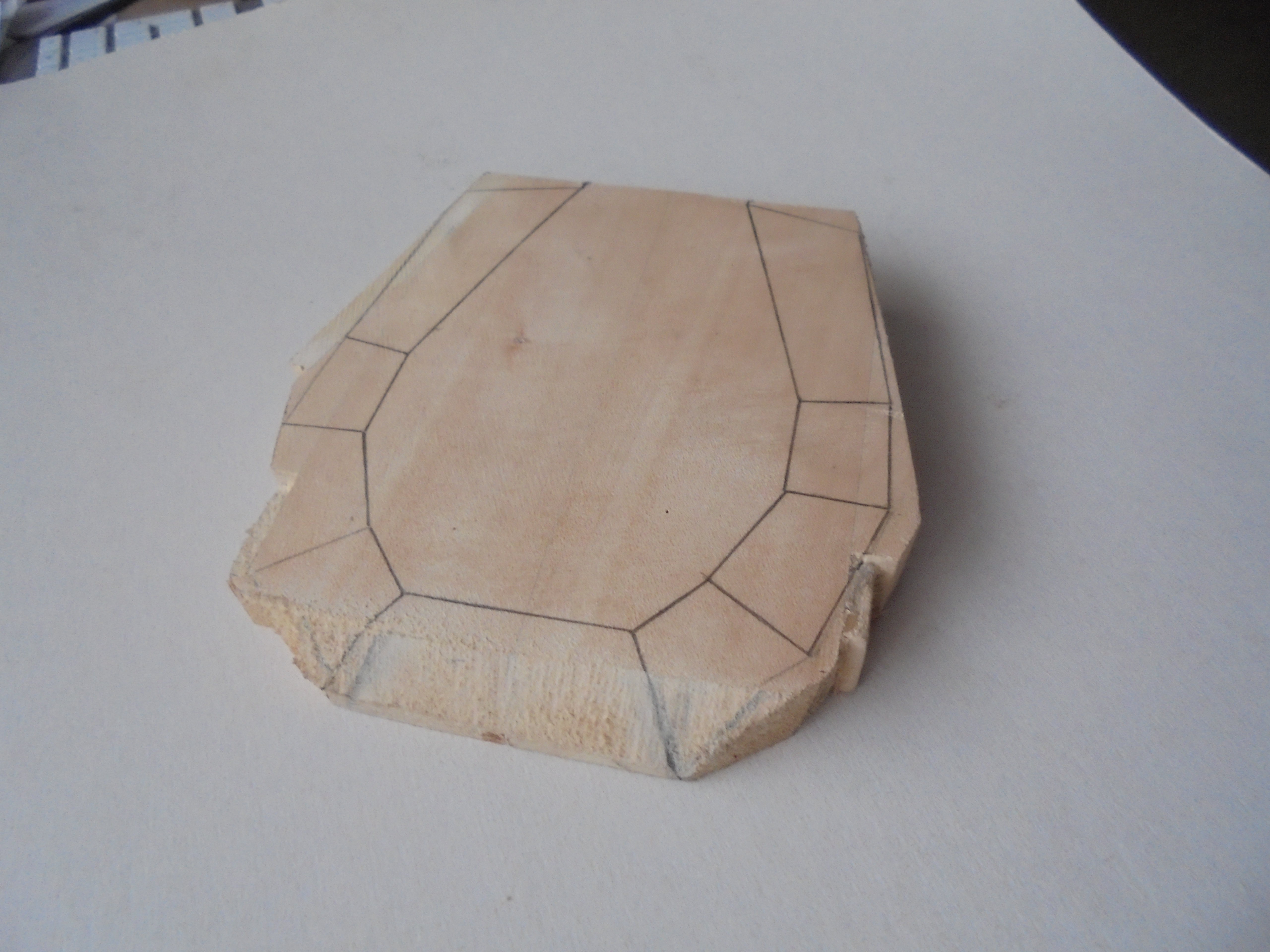
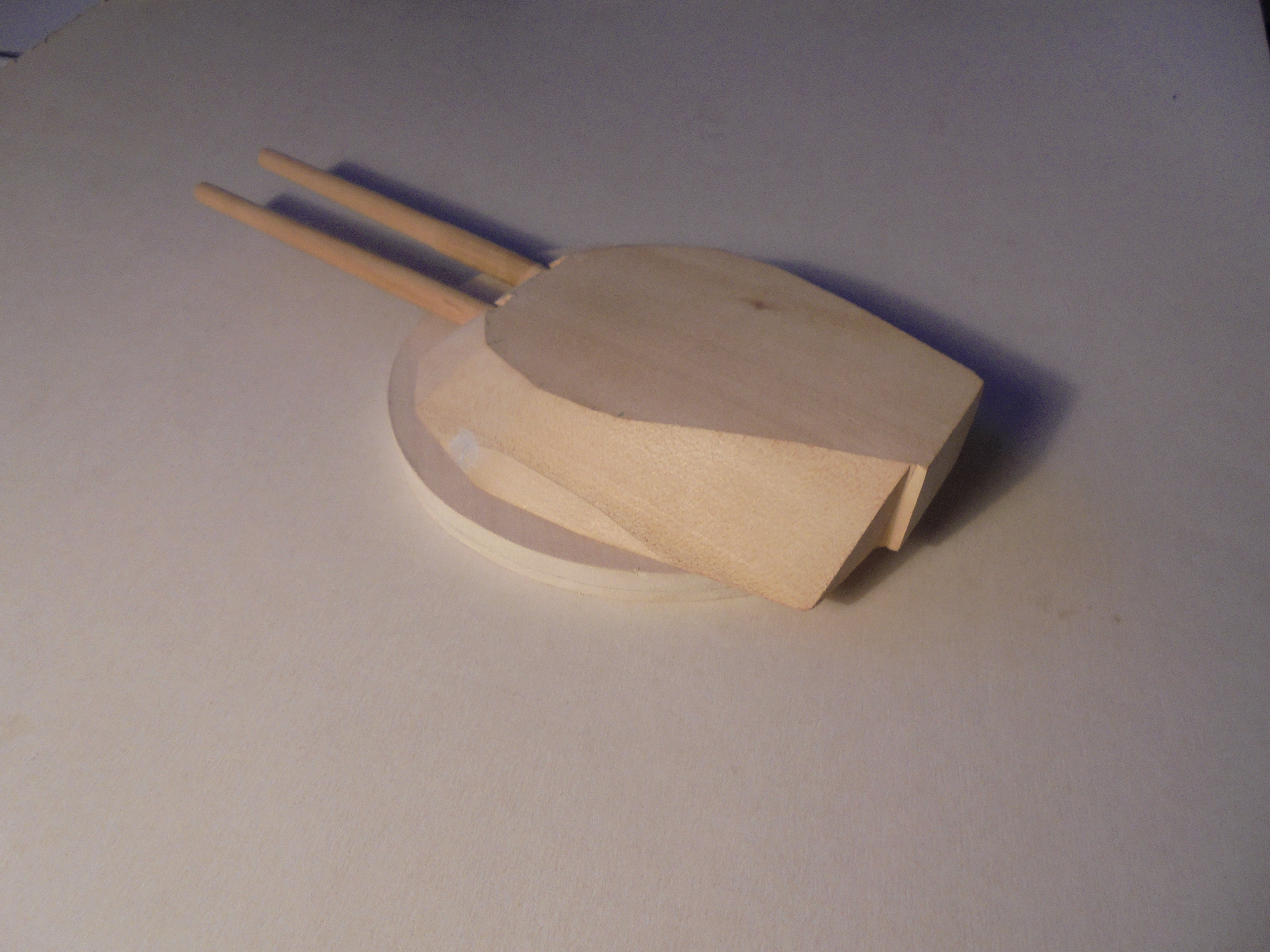
I made a block for the turret from 2 inch (5cm) square basswood: I cut a length of wood into two and glued the two pieces together and then added two more pieces of 1/4 inch sheet to the rear of the sides to allow for the wider rear of the turret. The top of the block was removed with a saw:


The front of the turret has also been trimmed to save filing the front face later. I filed/shaped the top of the turret first. I traced the upper and lower surfaces of the turret plan and the faces of the turret sides from the drawing and transferred these to the wood block and cut the sides of the block so that they were almost in alignment with the lower outline:

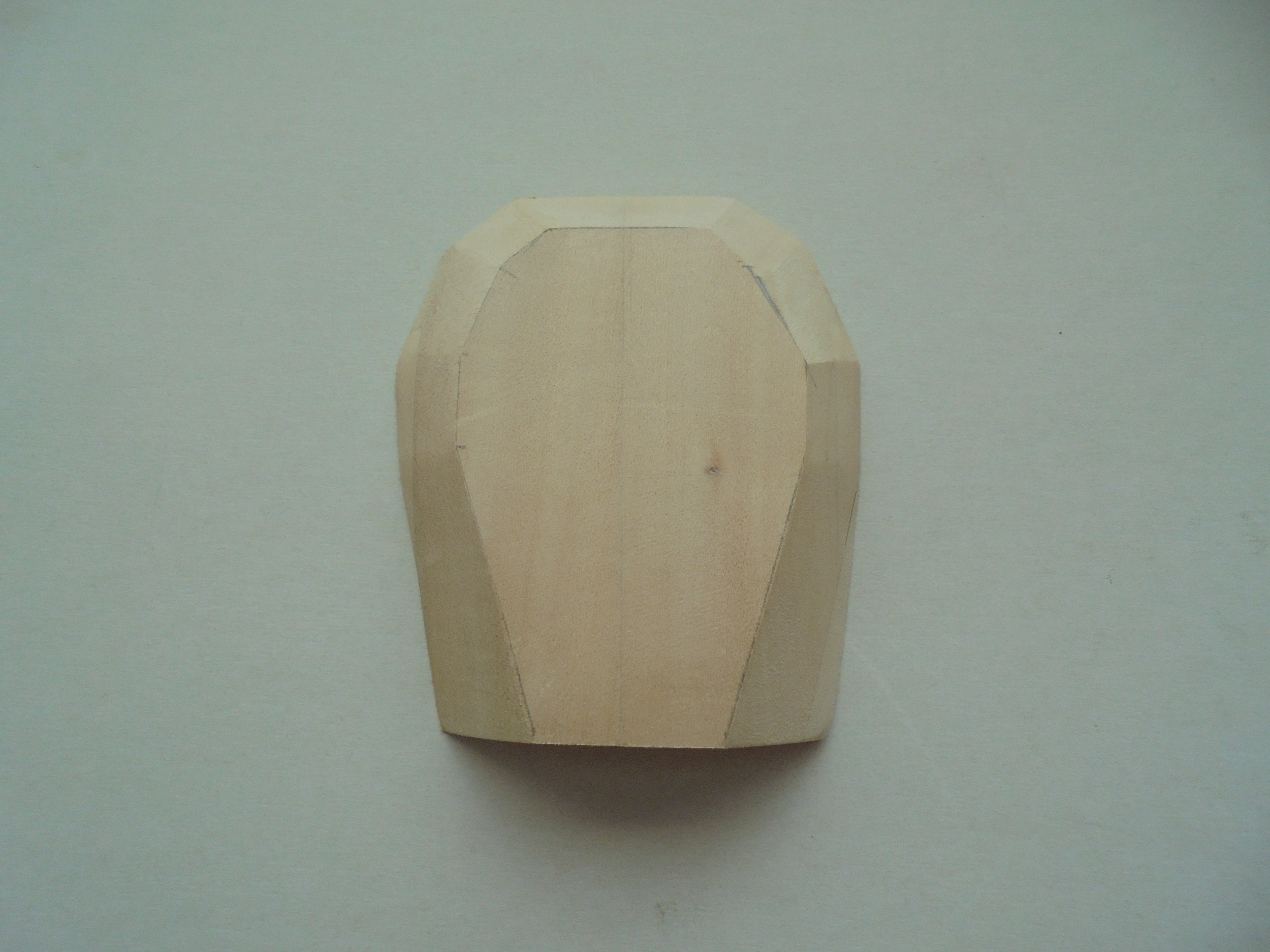
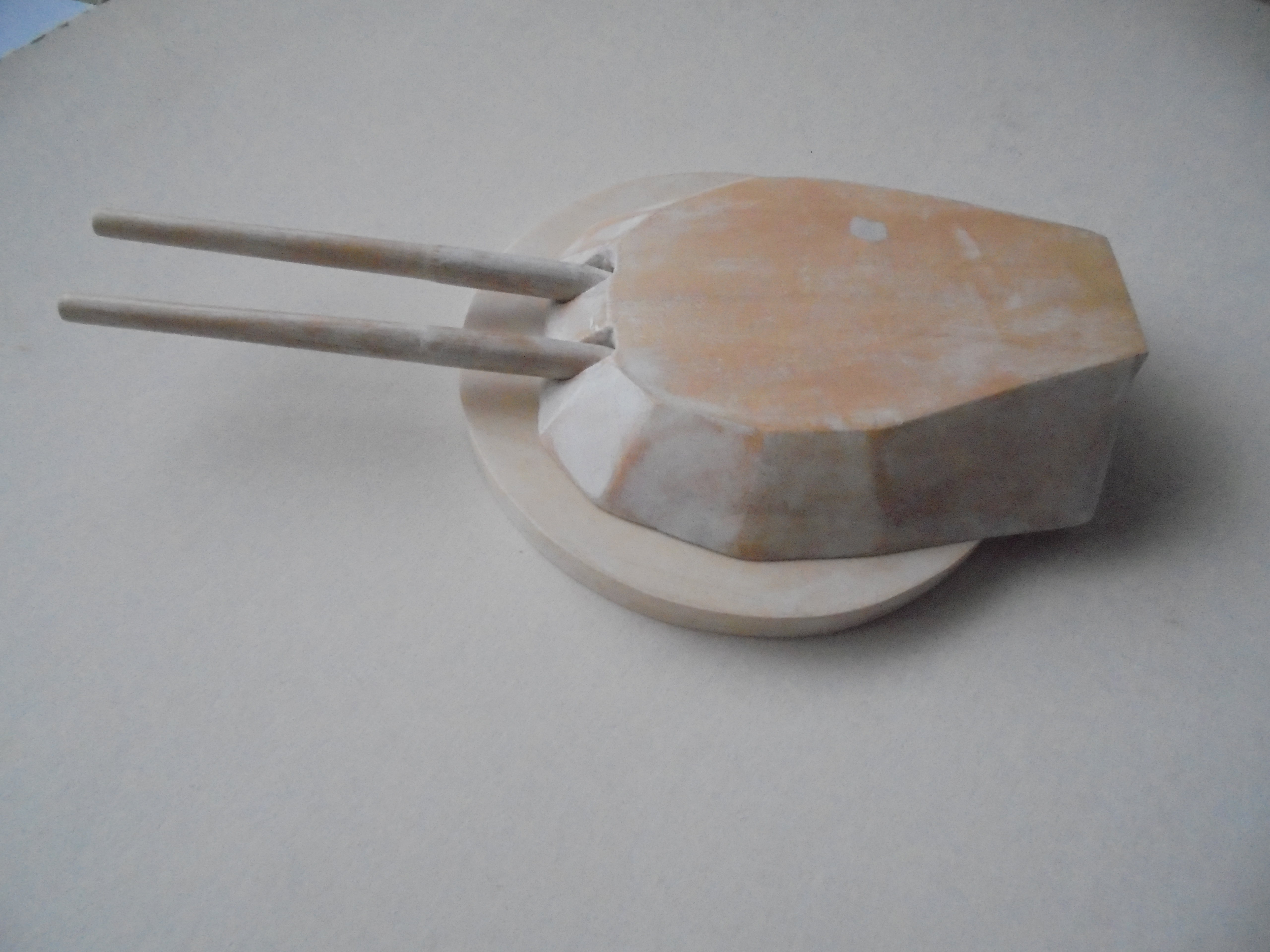
Starting at the rear I could now file the individual faces of one side of the turret using the lines as a guide:

The above operation was repeated for the other half of the turret and the front surface was also completed:
The rear of the turret had the recesses cut with a saw. I drilled two holes in the front of the turret to take the gun barrels. The barrels of the guns were made from pine dowel which had been turned in an electric drill and sanded to shape with coarse, and polished with fine, glasspaper. The ends were shaped to fit into the holes in the turret.

The turret, gun barrels and barbette were sealed with my go to wood sealant - talcum powder and dope mixture - and sanded smooth:
The gun barrels, turret and barbette have only been placed together for photos and checking fit and position. They will be permanently glued together later.

Thanks for looking.
Many thanks for your (too) kind comments - they are greatly appreciated. I have given a lot of thought to the undercarriage problem but cannot drill holes under the wing because in the front there is a strut in the way, and at the rear the boom is where the undercarriage leg is to be attached. I will probably have to use butt joints which are not the strongest attachment, but I am hoping that if the model is secured to the launch platform it will have sufficient strength to hold properly.
I have become a ship modeller recently: usually I make aeroplanes so I am learning fast. When I dropped into my LMS and asked for a kit of the front turret and foredeck of an Edwaed VII class battleship of 1912 in 1/72 scale I just received a blank stare! I started by downloading a plan and side elevation of the foredeck of HMS Africa/Hibernia and enlarged it until 1mm represents 1 foot. I could then draw a plan at 1/72 scale where 1 inch represents 6 feet.
I have made a base which is 12 inches (30 cm) x 11 inches (28cm) from hardboard and painted the edges which will not be covered by the deck white. I used white rather than sea blue because this will not be a waterline model: only the top of the ship sides above the portholes of the crew accommodation will be represented. Three supports from 1 inch x 1 inch (2.5cm x 2.5 cm) wood were glued to the top of the hardboard - these will hold the deck. I shaped 2 pieces of 1 inch square wood to represent the sides of the ship immediately below the deck line and covered the outer faces with 10 thou plastic sheet. These will be painted battleship grey later. The small fillets at the rear of the sides represent the curve of the ship sides above a 9.2 inch gun mounted low down in the hull:
The gaps at the front and rear of the model between deck and base will be covered with plastic card later. The deck was cut form 1/8th inch (2mm) basswood (lime) sheet: 2 pieces were cut and shaped to represent the deck forward of the bridge to a point approximately 30 feet (8.2m) forward of the forward barbette breakwater. The edges were rounded with glass paper and sealed with a mixture of talcum powder and dope:
The circle and arc represent where the barbette and breakwater will be positioned later. The curved rear covered the 9.2 inch guns in the hull and will have 60th plastic sheet CA'd underneath to represent the armoured deck.The top of the deck will be covered with 1/8 inch (2mm) square pine strip to represent the wood planking on the real ships. The barbette was cut form 4 pieces of 1/4 inch (0.5mm) basswood sheet: 2 pieces were joined to form a square sheet and the two sheets glued so that the joints were at 90 degrees. When the glue had set I cut off the waste wood around the circle that I had drawn on one surface, and the final rounding was achieved with a wood file:
I made a block for the turret from 2 inch (5cm) square basswood: I cut a length of wood into two and glued the two pieces together and then added two more pieces of 1/4 inch sheet to the rear of the sides to allow for the wider rear of the turret. The top of the block was removed with a saw:
The front of the turret has also been trimmed to save filing the front face later. I filed/shaped the top of the turret first. I traced the upper and lower surfaces of the turret plan and the faces of the turret sides from the drawing and transferred these to the wood block and cut the sides of the block so that they were almost in alignment with the lower outline:
Starting at the rear I could now file the individual faces of one side of the turret using the lines as a guide:
The above operation was repeated for the other half of the turret and the front surface was also completed:
The rear of the turret had the recesses cut with a saw. I drilled two holes in the front of the turret to take the gun barrels. The barrels of the guns were made from pine dowel which had been turned in an electric drill and sanded to shape with coarse, and polished with fine, glasspaper. The ends were shaped to fit into the holes in the turret.
The turret, gun barrels and barbette were sealed with my go to wood sealant - talcum powder and dope mixture - and sanded smooth:
The gun barrels, turret and barbette have only been placed together for photos and checking fit and position. They will be permanently glued together later.
Thanks for looking.
-
Clashcityrocker

- Modelling Gent and Scholar
- Posts: 10823
- Joined: May 1st, 2011, 12:31 am
- Location: Adelaide. South Australia
Re: Lone Modeller's Tray
Nigel
(words are not enough!)
-
Andy Dighton

- Modelling Gent and Scholar
- Posts: 2572
- Joined: November 25th, 2019, 7:21 pm
- Location: Kent.
Re: Lone Modeller's Tray
Awesome. That's all I have to say.
Best wishes
Andy
My post war RAF display team page. https://uamf.org.uk/viewtopic.php?f=201&t=19491"
XX172 Life of a BAe Hawk 1977-2006. https://uamf.org.uk/viewtopic.php?f=201&t=23975
Andy
My post war RAF display team page. https://uamf.org.uk/viewtopic.php?f=201&t=19491"
XX172 Life of a BAe Hawk 1977-2006. https://uamf.org.uk/viewtopic.php?f=201&t=23975
-
ShaunW
- NOT the sheep
- Posts: 26188
- Joined: November 26th, 2011, 6:11 pm
- Location: Pontefract West Yorkshire
Re: Lone Modeller's Tray
Wow, that is some seriously good ship modelling in wood there, LM, I'm in awe. I've no chance with the medium, my late father was a dab hand with wood but I haven't inherited those genes and am pretty hopeless with it. Put it this way, you really wouldn't want me to come round to yours to plane off your doors if they were rubbing the carpet - I'd stand a far better chance if the doors were made from plastic, I more or less know where I am with that 
Doing - Tamiya 1/35th Universal Carrier.
Work is the curse of the modelling classes!
IPMS#12300
Work is the curse of the modelling classes!
IPMS#12300

Re: Lone Modeller's Tray
Well explained and will be equally as good as your scratch built aircraft as well. Just remember you don't have to continue after the turret, you don't need to build the whole ship.
It's only pain, work through it.
-
Stuart
- Raider of the Lost Ark Royal
- Posts: 19451
- Joined: February 25th, 2013, 4:55 pm
- Location: North Wales
- Contact:
Re: Lone Modeller's Tray
That is a superb bit of work LM, that turret looks fabulous! Really interesting to see this come together, I was reading about the event you're building here in a local museum the other week - the pilots were certainly brave!
Stuart Templeton I may not be good but I'm slow...
My Blog: https://stuartsscalemodels.blogspot.com/
My Blog: https://stuartsscalemodels.blogspot.com/